ECMP next hop on Juniper M T and SRX series routers
 If like me, you have to jump around customer requirements, you may one day find yourself in a situation where you need to utilise capacity on 2 or more links between locations. My preference is to bond my uplinks with 802.1ax/802.3ad/LACP and let the upstream provider deal with the rest. Sometimes the providers let you down and can do nothing. They cant run LACP from their edge device to you, and they can’t transit your LACP frames so that you can perform your own LACP between locations. Also sometimes you have multiple links for different providers.
In this situation your last resort is Equal Cost Multi Path(ECMP) next hop. If you have a 2 or more routes in your routing table with exactly the same metrics and there are none that are more preferred, an ECMP decision is triggered. On Juniper routing platforms this is quite rudimentary in that one of the routes will be chosen (at random or based on src/dst hashes) for a particular route and installed in the FIB (the hardware forwarding engine). This means that the effectiveness of the traffic spread is limited to the number of routes in your table in a particular direction.
My typical implementation involves running OSPF between routers on each link with identical metrics. From the “remote” end of the network I do not aggregate the advertised prefixes, as this would reduce the pool of routes, and instead advertise all prefixes individually. This is often a whole bunch of /32 point to point customer IP’s and this is also partially why I choose to use OSPF for this.
Advertising from the core however is a bit more of a problem. Here typically you are advertising mainly the default route. There may be some peering routes that you have on either end and you may include those too, but typically you do not want to be sending a full table to some remote end of the network, as usually the reason you are here in the first place is that you are resource constrained.
The practical upshot is that traffic will balance ok in the direction towards the “remote” node, but very little or not at all inbound from the “remote” node. Typically this is the “download” direction and usually the direction most of the load is in in any case, but our situation is not ideal.
To achieve a better spread, and to not have to worry to much about how many routes you are using, you need to implement a policy on the forwarding table. I know it sounds like I made that up, but yes, thats a real thing. If you do not do this then your traffic spread/diversity will be constrained by the points discussed above.
So we create the policy..
set policy-options policy-statement my-default-balancing-policy then load-balance consistent-hash
And then apply it to the forwarding table..
set routing-options forwarding-table export my-default-balancing-policy
This will now let your traffic use all equal routes instead of just the selected one.
Your 2 balancing options are consistent-hash and per-packet. Per packet will send packets down each link in a round robin fashion and will result in nearly perfect load spread. However, this will cause out of order packet delivery between the sites as there will always be performance differences on the links which is why I never use it. The performance impact of out of order packets, on TCP specifically, is significant. The consistent-hash looks at the traffic IP source, destination and protocol fields and uses those values to calculate which link to use. This is good at keeping traffic flows on one path and packet delivery consistent.
ECMP algorithm choice on the MX series platform is performed quite differently, but many of the points discussed above are still valid. This is to be expected as the MX is a routing and switching platform so hashing at multiple layers is possible (L2/L3/L4) There are many more options to consider and we will leave that for another time.
A final note, the above hash looks at L3 information as a key for hashing and on an MPLS enabled network this may not be enough. You can also set ECMP options for MPLS with the following statement.
set chassis maximum-ecmp 16
Options are 16/32/64 and allow for up to that many alternate LSP to load balance across (thats if you have multiple LSP’s to your destination).
Monitoring HP G5 server hardware RAID on Debian
Personally I prefer to use Linux MDADM software raid because of the following factors
- Homogenous set of utilities, always the same, unlike all the different custom utils from all the many hardware vendors.
- Long term support for the platform.
- Proven performance and stability.
- Cheaper RAID cards use the CPU in any case and the MDADM implementation will blow it out the water for features/performance.
- Ability to run any type of RAID level unlike most hardware which usually only support 0,1 and 0+1.
But some times you get a system with decent dedicated controllers with cache and battery backup and you want to be able to offload to it. This is what was in my G5 system
lspci -nn
06:00.0 RAID bus controller [0104]: Hewlett-Packard Company Smart Array Controller [103c:3230] (rev 04)
Googling “pciid 103c:3230” quickly yielded that I was dealing with a “HP Smart Array P400i” card
Now while the card is supported by the OS out of the box an I can see any array that I created in the BIOS, the problem that I sit with is that I need to be able to monitor the disks for failure and issue rebuild commands without taking the system down. Trying to get this right with the vendor provided tools is usually near impossible as the vendor abandoned support and usually only had support for one or 2 commercial linux distros in any case. Enter the good folks at the HWraid project
Just add their repository and install the tools for your card (in this case the HP tools)
echo deb http://hwraid.le-vert.net/debian squeeze main >> /etc/apt/sources.list
apt-get update
apt-get install hpacucli
Now we test the tools.
hpacucli controller slot=0 physicaldrive all show
Smart Array P400i in Slot 0 (Embedded)

      physicaldrive 1I:1:1 (port 1I:box 1:bay 1, SATA, 500 GB, OK)
      physicaldrive 1I:1:2 (port 1I:box 1:bay 2, SATA, 500 GB, OK)
Success.. now that I have the tools that can interrogate the controller, I need to build some monitoring, so I add a script which I schedule to run every hour in cron.
#!/bin/bash
MAIL=noc@acme.com
HPACUCLI=`which hpacucli`
HPACUCLI_TMP=/tmp/hpacucli.log

if [ `$HPACUCLI ctrl all show config | grep -E 'Failed|Rebuilding'| wc -l` -gt 0 ]
then
msg="RAID Controller Errors"
logger -p syslog.error -t RAID "$msg"
$HPACUCLI ctrl all show config > $HPACUCLI_TMP
mail -s "$HOSTNAME [ERROR] - $msg" "$MAIL" < $HPACUCLI_TMP
echo $msg
cat $HPACUCLI_TMP
rm -f $HPACUCLI_TMP
fi
Configure your mail subsystem and ensure your system is actually able to send mail.
dpkg-reconfigure exim4-config
The script is very basic but it gets the job done, and yes you will generate alerts every hour if there is an issue until its resolved, think of it as a feature. The script sends a mail to the hardcoded email address as well as adds it to your syslog. If you are performing syslog monitoring and alerts with something like Solarwinds, Splunk or Graylog then you could rather depend on those systems for alerts by checking for the alert message in syslog and scrap the emailing bit of the script.
Juniper M10 value propositon
The Juniper M series of routers have been obsoleted but are a really good value proposition if all you need is a few gig of reliable routing capability. The M10/M10i is a redundant H/A solution that is readily available in the refurbished market from sub 2000 USD and the most cost effective way to bootstrap a small enterprise with a robust core.
What You Get
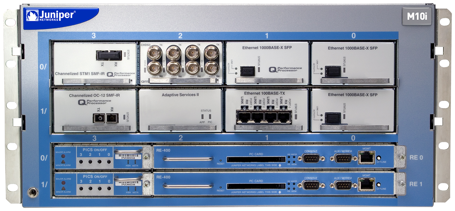
- 5U Chassis
- 2 x C-FEB Forwarding Boards (active + standby)
- 8 x PIC Physical Interface Card slots
- 2 x Routing Engines 400Mhz CPU 256M RAM (higher spec available for more $)
- 4 x 300W PSU (2 Required for operation 3/4 for redundancy)
- In Service replaceable fan tray
Pro’s
- Fully redundant PSU, routing engine and switch fabric.
- High availability features
- Cheap and available
- Enterprise grade
- MPLS and IPV6 support
- Dedicated out of band ethernet and RS232 management ports
- Plenty of SONET/SDH/ATM PIC options at reasonable pricing
Con’s
- Limited capacity (1G per PIC/slot)
- Relatively inefficient (power and size vs throughput)
- End Of Life
- No layer-2 capability (kind of.. see below)
- Only vlan-tagging support, no stacked-vlan-tagging or flexible-vlan-tagging (ie. no L3 support for Q-in-Q).
The 1G limitation per port is the hard limit on this device and I would not want to try and use it anywhere beyond a total of 4G of capacity as balancing evenly across ports starts to become a factor. The M series routers are IP/MPLS routers supporting all the standard BGP/IS-IS/OSPF and MPLS protocols as well as allowing for multiple routing instances.
Stateful firewalling and VPN is possible but would require a services PIC, two for redundancy. If this is what you are needing then you are generally better off looking at something else as they can be expensive and limited to 1G per module.
Now the M series were made in an era when layer-2 and layer-3 functionality was typically serviced by separate devices, so the M series routers are just that, routers, they have no switching capability at all. Well kind of, it support 802.3ad LACP link bonding between PIC’s and with the progression of technology and standards, Junos and the M platform received upgrades and features which included MPLS and VPLS functionality which is technically a layer-2 technology.
Because of the lack of switching support VPLS is limited in what it can do and you can run into issues if you are not aware of of these limitation. How we typically implement is as follows
- 4 x 1G ethernet PIC’s
- 2 x 2 Ports bonded with LACP into 2 aggregated ethernet ports on switches
(these numbers can be doubled for more capacity)
We use the 2 aggregated ports to provide a network facing port and a services facing port. They also provide link redundancy into the network, they typically all uplink into the same switch stack and are used to provide a pair of interfaces/VLAN’s for the M10 which can also be used to loop traffic where required. You could do this all with one AE port with all the physicals in it and just use VLANs but I like to split my roles across interfaces for easier visibility and troubleshooting.
So on one VLAN on the network AE we set up MPLS capability with all the layer-3 stuff that’s required to make MPLS work. On the services port we setup a customer or service facing VLAN that we want to tunnel using VPLS. This is done by setting the VLAN port encapsulation to vlan-vpls and then creating a routing instance of instance-type vpls and adding the interface to that instance type. Now this is technically a switching function that is being performed on a routing only device.
The caveat is that you need to create a separate routing instance for every layer-2 service that you want to use. You CANNOT use VLAN’s on the VPLS service because you will run into MAC learning issues due to the fact that the M10 is not layer-2 aware and cannot differentiate between the different broadcast domains of multiple VLAN’s. It will work for a bit but you will run into random dropped packets as the MAC learning table on your endpoint devices gets polluted.
The flexible-vlan-tagging or stacked-vlan-tagging option on interfaces is allowed but ultimately not supported. On commit the device spits warnings in the messages log and when you try and configure the inner and outer tag the router will not accept the configuration. You should configure the vlan-tagging option instead.
A simpler supported L2 feature is the l2circuit using MPLS. It is a point to point only tunnel that does not perform any MAC learning whatsoever, it just take the frame on one side and spits it out on the other. This can be configured on VLANs on ethernet ports if the encapsulation type on the VLAN is set to vlan-ccc. The port will accept further tags if they are present as well as “L2 local” frames such as LACP,LLDP,STP BPDU’s etc… The service is only really limited by overall MTU. This is because the M10 is not involved in any L2 learning so it will transparently pass the frame from one endpoint to the other endpoint. This is also why you can only have one endpoint because the M10 cannot make a path determination with no address information.
The down side is that troubleshooting can be a bit harder in that you cannot see any learned MAC’s but the up side is that you do not need to worry about memory + MAC learning limits.
As mentioned above, the lack of L2 support means that we usually pair an M10 with 2 EX4200’s in VC mode. QFX would be better but we are looking at a budget solution here so they don’t make sense. This gives you a certain amount of L2 flexibility that will cover most use cases. Be aware that EX series switches only support VLAN swap and push functions NOT VLAN pop. This can be somewhat limiting in this environment. One final note regarding the EX configuration for l2circuits, you can configure “dot1-tunneling layer2-protocol-tunneling all” on the EX4200’s which will ensure you can transparently take all frames from a customer facing VLAN to a l2circuit on the M10. This is also where we can look at MAC learning for troubleshooting as the switch will learn customer MAC’s, and also where we set MAC learning limits to prevent possible issues introduced on the EX by customer networks.
Saving IP space on your point to point peering subnets using /31 subnets aka RFC3021
Most of us are used to allocating a /30 subnet for point to point peering, which gives us 2 device IP’s, a network address, and a broadcast address. With the exhaustion of IPV4 space it’s useful to be able to save wherever you can, so where possible you should consider /31 allocation instead of /30. Most modern day vendors support RFC3021 and using it is as simple as just specifying the /31 subnet mask. I have used this on various Juniper and Cisco devices in the past without any issues, but unfortunately not all vendors or models support it so your mileage will vary.
I would also, always recommend performing further testing beyond just a ICMP reachability tests if broadcast protocols are involved. A prime example is if you use something like the OSPF routing protocol that uses broadcast as a discovery mechanism. It should work but if it does not then possibly see if you can set it o P2P operation before reverting back to a /30 allocation.
I need to mention Mikrotik specifically here because they do not support RFC3021 in an obvious way. If you just specify x.x.x.x/31 it wont work. You need to specify a /32 with a matching network address. So 1.1.1.0/31 would look like so
/ip address add address=1.1.1.0/32 network=1.1.1.1 interface=ether1
The above example is compatible with RFC3021 but is actually different in that the network address does not have to fall within the same /31 as the IP. I have struggled to find the RFC for this assignment scheme but it allows you to be able to add the same IP multiple times with a different network address. This allows you to reach multiple devices on the same network segment using only a single IP per device. This obviously only works if all devices support this format.
Example of using this to connect to 2 other routers with IP’s 2.2.2.2 and 3.3.3.3.
/ip address add address=1.1.1.0/32 network=2.2.2.2 interface=ether1
/ip address add address=1.1.1.0/32 network=3.3.3.3 interface=ether1
“Stealing” a single IP from a subnet that you do not control.
The requirements to do weird and wonderful things never cease when it comes to networking and unprepared clients. I won’t go into the why, but I will share with you an interesting hack that I have not really seen done elsewhere. Here is the scenario, I have a DMZ subnet and a DMZ router lets say on 1.1.1.0/28, I want to take one of those IP’s and terminate it on another device without using NAT. Now here is the trick, the device in question sits one or more routed hops away and I DO NOT have access to the DMZ router.
This is especially useful when you want a device to actually have the IP terminated on it, and you want to avoid NAT because of ALG issues (eg SIP.).
You will need..
- 1x Mikrotik router (in my case it was a virtual x86 one in a VM)
- 1x Interface in the DMZ
- 1x Interface in the “Other” network
- Enable proxy-arp on the DMZ interface
- Set up a filter to only deal with the arps you are interested in
The filter functionality we need to use on Mikrotik is only available under the bridging firewall (which is the equivalent of ebtables for all the netfilter people), so we need to use a bridge interface for the filtering to work. We filter because we don’t want to introduce a device that responds to all ARP requests on the network. Introducing new behaviour in a system may break something so avoid it where possible.
Possibly scenarios are.. an IP scanning security appliance performs network scans and detects all these new active IP’s and then raises false alarms or.. possibly there is another device on the segment also performing proxy-arp so as to make something work and introducing another proxy-arp device will break that. Cisco IOS configurations found in X.21 routers (and probably others) seem to like to enable proxy-arp by default, I never did like this and still to this day find them scattered around corporate environments.
Lets use the following IP’s in the example.
- 1.1.1.1 DMZ router IP, aka the gateway to the internet
- 1.1.1.3 Router IP, we strictly don’t need this but you probably want to allocate an IP to the router so that you can manage it.
- 1.1.1.5 IP we want to steal/route onwards
- 192.168.50.1/24 Router IP on the private network that the hosted device sits on
- 192.168.50.12/24 IP of the device that needs to host the “stolen” IP
So lets get started by creating the bridge and enabling proxy-arp on it.
/interface bridge
add arp=proxy-arp name=br-dmz protocol-mode=none
/interface bridge port
add bridge=br-dmz interface=ether1
Lets number the interfaces
/ip address
 add address=1.1.1.3/28 interface=br-dmz
 add address=192.168.50.1/24 interface=ether2
Then we add the ARP filters that accept ARP requests for the router IP and the forwarded IP only.
/interface bridge filter
 add arp-dst-address=1.1.1.3/32 arp-opcode=request chain=input \
 mac-protocol=arp
 add arp-dst-address=1.1.1.5/32 arp-opcode=request chain=input \
 mac-protocol=arp
 add action=drop arp-opcode=request chain=input log=yes mac-protocol=arp
If you are using VLAN instead on physical interfaces you may need to enable
/interface bridge settings
 set use-ip-firewall-for-vlan=yes
OK, so now we have the “stolen” the IP lets send it to the device that we want host it on
/ip route
 add distance=1 dst-address=1.1.1.5/32 gateway=192.168.50.12
 add distance=1 dst-address=0.0.0.0/0 gateway=1.1.1.1
I wont go into how you get the host to use the IP as a source address for originating outgoing connections, but as it stands if you install 1.1.1.5/32 on an active physical interface or on a loopback interface(recommended) of the device, most devices will work from an inbound connection perspective (ie they will be reachable on that IP). I cannot really cover outgoing source address selection, as this will vary depending on the device and OS. but in most cases I would look to see if you can set a “preferential source address” attribute on the default route of the devices routing table.